春风十里不如你 —— Taozi - 配置 2023-06-05T16:52:18+08:00 Typecho https://www.xiongan.host/index.php/feed/atom/tag/%E9%85%8D%E7%BD%AE/ <![CDATA[【HCIP】MSTP的基础配置]]> https://www.xiongan.host/index.php/archives/214/ 2023-06-05T16:52:18+08:00 2023-06-05T16:52:18+08:00 admin https://www.xiongan.host MSTP基础配置

实验组网:

1685929880897

1685929641484

实验步骤:

根据上图中的信息,进行配置PC机的ip和子网掩码,然后保存应用

配置交换机S1的Vlan

//在交换机S1上创建VLAN 10与20,并将连接PC的端口配置成为Access类型接口,划入相应VLAN。交换机间的接口配置成为Trunk接口,允许所有VLAN 通过。
<Huawei>system-view
[Huawei]sysname S1
[S1]vlan batch 10 20 
[S1]interface Ethernet0/0/3 
[S1-Ethernet0/0/3]port link-type access 
[S1-Ethernet0/0/3]port default vlan 10
[S1-Ethernet0/0/3]interface Ethernet0/0/1
[S1-Ethernet0/0/1]port link-type trunk 
[S1-Ethernet0/0/1]port trunk allow-pass vlan all
[S1-Ethernet0/0/1]interface Ethernet0/0/2
[S1-Ethernet0/0/2]port link-type trunk
[S1-Ethernet0/0/2]port trunk allow-pass vlan all

配置交换机S2的Vlan

//在交换机S1上创建VLAN 10与20,并将连接PC的端口配置成为Access类型接口,划入相应VLAN。交换机间的接口配置成为Trunk接口,允许所有VLAN 通过。
<Huawei>system-view
[Huawei]sysname S1
[S1]vlan batch 10 20 
[S1]interface Ethernet0/0/3 
[S1-Ethernet0/0/3]port link-type access 
[S1-Ethernet0/0/3]port default vlan 10
[S1-Ethernet0/0/3]interface Ethernet0/0/1
[S1-Ethernet0/0/1]port link-type trunk 
[S1-Ethernet0/0/1]port trunk allow-pass vlan all
[S1-Ethernet0/0/1]interface Ethernet0/0/2
[S1-Ethernet0/0/2]port link-type trunk
[S1-Ethernet0/0/2]port trunk allow-pass vlan all

配置交换机S3的Vlan

//在交换机S3上创建VLAN 10与20,并将连接PC的端口配置成为Access类型接口,划入相应VLAN。交换机间的接口配置成为Trunk接口,允许所有VLAN 通过。
<Huawei>system-view
[Huawei]sysname S3
[S3]vlan batch 10 20
[S3]interface Ethernet0/0/3
[S3-Ethernet0/0/3]port link-type access 
[S3-Ethernet0/0/3]port default vlan 10
[S3-Ethernet0/0/3]interface Ethernet0/0/4
[S3-Ethernet0/0/4]port link-type access 
[S3-Ethernet0/0/4]port default vlan 20
[S3-Ethernet0/0/4]interface Eth0/0/1 
[S3-Ethernet0/0/1]port link-type trunk 
[S3-Ethernet0/0/1]port trunk allow-pass vlan all
[S3-Ethernet0/0/1]interface Ethernet0/0/2
[S3-Ethernet0/0/2]port link-type trunk 
[S3-Ethernet0/0/2]port trunk allow-pass vlan al

理解MSTP的运行机制及验证单实例

当网络管理员按照设计搭建完公司二层网络后,启动设备。在华为交换机上默认即运行MSTP协议。

检查S1 STP状态信息在S1上使用stp root primary命令设置为根桥,然后使用命令display stp检查生成树的状态和统计信息

可以观察到,在CIST全局信息中,显示目前STP模式为MSTP,根交换机为S1自身,另外还有交换机各个接口上的STP信息。

1685931155396

检查S1 STP摘要信息

使用命令display stp brief检查S1上生成树的状态和统计的摘要信息

可以观察到,此时S1上的端口都为指定端口,且都处于转发状态,为根交换机。

1685931298819

检查S2 STP摘要信息

在S1上使用stp root secondary命令设置为次优根桥,然后使用命令display stp brief检查S2上生成树的状态和统计的摘要信息。

1685931382611

检查S3 STP摘要信息

使用命令display stp brief检查S3上生成树的状态和统计的摘要信息。

1685931472094

可以观察到,S3上的E 0/0/2为替代端口,处于丢弃状态。

MSTID,即MSTP的实例ID,三台交换机上目前都为0,即在默认情况下,所有VLAN都处于MSTP实例0中。

假如网络管理员配置STP模式为RSTP,最终选举出来的根交换机及被阻塞的端口等结果将和目前MSTP的选举结果一致,即在MSTP的单个实例中,选举规则与RSTP一致,端口角色与状态与RSTP也一致。

在PC2、PC4上发包

PC2:ping 192.168.10.1 -t

PC4:ping 192.168.20.1 -t

在S3的e0/0/1抓包

可以观察到,目前VLAN 10和VLAN 20的数据包都从S2的接口E 0/0/1转发

1685931956583

在S3的E0/0/2抓包

1685932111395

可以观察到,在S3的E 0/0/2接口上,没有任何数据包转发,只接收到上行接口周期发送的BPDU。

此时S2与S3间的链路完全处于闲置状态,造成了资源的浪费,也导致了S1与S3间链路上数据转发任务繁重,易引起拥塞丢包。

为了能够有效的利用链路资源,可以通过配置MSTP的多实例来实现。 关闭PC上的ping测试。

配置MSTP多实例

//配置S1 MSTP域
使用命令stp region-configuration进入MST域视图。
[S1]stp region-configuration 
[S1-mst-region]
使用命令region-name 配置MST域名为huawei。
[S1-mst-region]region-name huawei
使用命令revision-level 配置MSTP的修订级别为1。
[S1-mst-region]revision-level 1
使用命令instance指定VLAN 10映射到MSTI 1,指定VLAN 20映射到MSTI 2。
[S1-mst-region]instance 1 vlan 10
[S1-mst-region]instance 2 vlan 20
使用命令active region-configuration 激活MST域配置。
[S1-mst-region]active region-configuration Info: This operation may take a few seconds. Please wait for a moment...done.
激活域后,配置S1为两个实例的根桥。
stp instance 1 root primary
stp instance 2 root primary
//配置S2 MSTP域
在S2上做同样配置,注意,在同一MST域中,必须具有相同域名,修订级别,以及VLAN到MSTI的映射关系。激活域后,配置S2为两个实例的次优根桥。
[S2]stp region-configuration 
[S2-mst-region]region-name huawei
[S2-mst-region]revision-level 1
[S2-mst-region]instance 1 vlan 10 
[S2-mst-region]instance 2 vlan 20
[S2-mst-region]active region-configuration 
//配置S3 MSTP域
在S3上做同样配置,注意,在同一MST域中,必须具有相同域名,修订级别,以及VLAN到MSTI的映射关系。 [S3]stp region-configuration  
[S3-mst-region]region-name huawei 
[S3-mst-region]revision-level 1 
[S3-mst-region]instance 1 vlan 10 
[S3-mst-region]instance 2 vlan 20 
[S3-mst-region]active region-configuration 

检查S1、S2、S3 MST域配置信息

1685934303959

1685934329465

1685934361190

在PC2、PC4进行发包,抓包s3的e0/0/1、e0/0/2

PC2:ping 192.168.10.1 -t

PC4:ping 192.168.20.1 -t

1685935028464

可以观察到,目前VLAN 10和VLAN 20的数据包仍然从E 0/0/1转发。

1685935093934

在S3的E 0/0/2接口上抓包观察。

可以观察到,在E 0/0/2接口上,仍然没有任何数据包转发,只有接收到的上行接口周期发送的BPDU。

关闭PC上的ping测试。

现在已经配置了MSTP多实例,但由于每个MSTP实例都是单独的一颗生成树,独立进行选举,所以在默认不变动任何生成树参数的情况下,其实每棵生成树的选举结果是一致的。

检查实例信息

1685935294606

在S1上使用命令display stp instance 0 brief检查默认实例0中的生成树状态和统计的摘要信息。

1685935604088

在S2上使用命令display stp instance 0 brief检查默认实例0中的生成树状态和统计的摘要信息

1685935333080

在S3上使用命令display stp instance 0 brief检查默认实例0中的生成树状态和统计的摘要信息。

1685935392008

在S1上使用命令display stp instance 1 brief检查实例1中的生成树状态和统计的摘要信息。

1685935660623

在S2上使用命令display stp instance 1 brief检查实例2中的生成树状态和统计的摘要信息。

1685935795613

可以观察到,在三个实例中,选举结果是一致的,都是S3的E 0/0/2接口处于Discarding状态。 现在要实现S2与S3间的链路被利用,可以在实例1中,保持目前生成树选举结果不变,即使得VLAN 10中的HR部门内的流量通过S1与S3间的链路转发。在实例2中,配置使得S2成为根交换机,阻塞S1与S3间的链路,即使得VLAN 20中的IT部门的流量通过S2与S3间的链路转发。

配置S2在实例2中为根

//在S2上使用命令stp instance priority配置其在实例2中的优先级为0,成为实例2中的根交换机。 
[S2]undo stp instance 2 root 
[S2]stp instance 2 priority 0

再次查看S1实例2的信息

1685936075072

再次检查S3实例2信息

1685936122910

可以观察到,此时S2成为了实例2中的根交换机,所有端口都为指定端口,而S3的E0/0/1接口为替代端口,即S1与S3间的链路现已阻塞。

在PC2、PC4上发包

PC2>ping 192.168.10.1 -t

PC4>ping 192.168.10.1 -t

抓S3的e0/0/1接口

1685936261194

可以观察到,目前VLAN 10的流量都从S3的E0/0/1接口转发。

抓S3的e0/0/2接口

1685936322042

可以观察到,目前VLAN 20的流量都从E0/0/2接口转发。 至此,完成了MSTP的多实例的配置,并达到了流量分担的目的,有效的利用了网络资源,也同时使得S3的两条上行可以互相备份。

]]>
<![CDATA[【ENSP】RSTP和MSTP基础配置]]> https://www.xiongan.host/index.php/archives/209/ 2023-05-22T19:00:23+08:00 2023-05-22T19:00:23+08:00 admin https://www.xiongan.host RSTP、MSTP基础配置

实验组网

1684719281673

任务步骤

设备开启STP,并将STP模式切换为RSTP

[S1]stp enable
[S1]stp mode rstp
[S2]stp enable
[S2]stp mode rstp
[S3]stp enable
[S3]stp mode rstp
[S4]stp enable
[S4]stp mode rstp

1684720282267

查看STP的状态和统计信息摘要

1684720489701

1684720513926

1684720543670

1684720568088

在S1上查看STP的状态和统计信息(S1为根桥交换机)

1684720917704

根桥选举控制

配置S1为主根桥,S2为备份根桥

[S1]stp priority 4096
[S2]stp priority 8192

在另外两台交换机保持默认桥优先级(32768)的情况下,S1拥有最小的桥优先级,S2次之。

再次查看S1上的状态信息(此时S1的桥优先级为4096,并且此时仍然是根桥)

1684721119496

取消S1、S2上手动调整桥优先级的配置,使用stp root命令指定根桥和备份根桥

[S1]undo stp priority
[S1]stp root primary
[S2]undo stp priority
[S2]stp root secondary

查看S1和S2的stp状态信息

1684721311217

1684721329737

S1的桥优先级为0,而S2的桥优先级为4096,此时S1为根桥,S2为备份根桥。

修改接口开销控制根端口选举

在S4上查看stp状态和统计信息

1684721474502

S4上0/0/2拥有更小的RPC(根路径开销),从而成为根端口

查看S4的0/0/2的STP状态和统计信息

1684721623276

此时路径开销计算方法为Dotlt,接口的STP cost的值为20000

修改S4的0/0/2的STP cost值为40001

[S4]interface g0/0/2
[S4-GigabitEthernet0/0/2]stp cost 40001
[S4-GigabitEthernet0/0/2]

查看s4的STP状态信息

1684721879063

此时0/0/1的RPC为40000,小鱼0/0/2的RPC 40001 S4的0/0/1接口成为根端口

修改接口优先级控制根端口选举

查看S2的STP状态信息

1684722038120

S2上GE0/0/10、GE0/0/11接口收到的BPDU拥有相同的RPC、网桥ID、接口优先级,此时将会比较接收到的BPDU接口ID中的接口编号。

在S1、S2上开启LLDP,查看接口的互联关系

[S1]lldp enable
[S2]lldp enable
[S2]display lldp neighbor brief

1684722179609

S2的GE0/0/10接口对端为S1的GE0/0/10接口,S2的GE0/0/11接口对端为S1的GE0/0/11接口,S2的GE0/0/10接口接收到的BPDU拥有更小的接口编号,这是GE0/0/10成为根端口的原因

在S1上修改GE0/0/11的STP接口优先级,使其发送的BPDU优于 GE0/0/10发送的BPDU

[S1]interface GigabitEthernet 0/0/11
[S1-GigabitEthernet0/0/11] stp port priority 64

STP接口优先级为128,数值越小越优。

再次查看S2的stp状态信息

1684722305430

此时S2的GE0/0/10接口成为根端口。

MSTP基础配置

在所有交换机上创建VLAN10、20、30、40、50、60、70、80,配置MSTP域hcip,并创建两个新的实例:Instance 1、Instance 2,将VLAN10、30、50、70映射到Instance 1,将VLAN20、40、60、80映射到Instance 2,同时将SW1规划为MSTI1的主根桥、MSTI2的备份根桥,将SW2规划为MSTI2的主根桥、MSTI1的备份根桥。

[S1]vlan batch 10 20 30 40 50 60 70 80
[S2]vlan batch 10 20 30 40 50 60 70 80
[S3]vlan batch 10 20 30 40 50 60 70 80
[S4]vlan batch 10 20 30 40 50 60 70 80

将所有的互联接口(S1、S2、S3、S4)配置为Trunk接口,放通所有的(接口端口)Vlan

interface GigabitEthernet0/0/10
 port link-type trunk
 port trunk allow-pass vlan 10 20 30 40 50 60 70 80
#
interface GigabitEthernet0/0/11
 port link-type trunk
 port trunk allow-pass vlan 10 20 30 40 50 60 70 80
 stp instance 0 port priority 64
#
interface GigabitEthernet0/0/12
 port link-type trunk
 port trunk allow-pass vlan 10 20 30 40 50 60 70 80
#
interface GigabitEthernet0/0/13
 port link-type trunk
 port trunk allow-pass vlan 10 20 30 40 50 60 70 80

修改STP模式为MSTP

[S1]stp mode mstp
[S2]stp mode mstp
[S3]stp mode mstp
[S4]stp mode mstp

配置MSTP

[S1]stp region-configuration
[S1-mst-region] region-name hcip
[S1-mst-region] revision-level 1
[S1-mst-region] instance 1 vlan 10 30 50 70
[S1-mst-region] instance 2 vlan 20 40 60 80
[S1-mst-region] active region-configuration
Info: This operation may take a few seconds. Please wait for a moment...done.
[S1-mst-region] quit
/
[S2]stp region-configuration
[S2-mst-region] region-name hcip
[S2-mst-region] revision-level 1
[S2-mst-region] instance 1 vlan 10 30 50 70
[S2-mst-region] instance 2 vlan 20 40 60 80
[S2-mst-region] active region-configuration
Info: This operation may take a few seconds. Please wait for a moment...done.
[S2-mst-region] quit
/
[S3]stp region-configuration
[S3-mst-region] region-name hcip
[S3-mst-region] revision-level 1
[S3-mst-region] instance 1 vlan 10 30 50 70
[S3-mst-region] instance 2 vlan 20 40 60 80
[S3-mst-region] active region-configuration
Info: This operation may take a few seconds. Please wait for a moment...done.
[S3-mst-region] quit
/
[S4]stp region-configuration
[S4-mst-region] region-name hcip
[S4-mst-region] revision-level 1
[S4-mst-region] instance 1 vlan 10 30 50 70
[S4-mst-region] instance 2 vlan 20 40 60 80
[S4-mst-region] active region-configuration
Info: This operation may take a few seconds. Please wait for a moment...done.
[S4-mst-region] quit

在S1上检查MSTP实例和Vlan的映射关系

1684722873417

//配置SW1为MSTI1的根桥、MSTI2的备份根桥
[S1]stp instance 1 root primary 
[S1]stp instance 2 root secondary
//配置SW2为MSTI2的根桥、MSTI1的备份根桥
[S2]stp instance 1 root secondary 
[S2]stp instance 2 root primary

在S1上查看MST1状态信息

1684724119504

S1上所有接口都是指定接口,S1为MSTI1的根桥

1684724164486

S2上所有接口都是指定接口,S2为MSTI2的根桥。

]]>
<![CDATA[【Ha-proxy】负载均衡配置实践记录]]> https://www.xiongan.host/index.php/archives/55/ 2022-10-15T12:18:00+08:00 2022-10-15T12:18:00+08:00 admin https://www.xiongan.host ha-proxy概述

ha-proxy是一款高性能的负载均衡软件。因为其专注于负载均衡这一些事情,因此与nginx比起来在负载均衡这件事情上做的更好,更专业。

准备

主机部署

Proxy端需要安装openssl openssl-lib haproxy

Web01和02 只需要安装httpd即可

Proxy端:

先备份配置文件
mv /etc/haproxy/haproxy.cfg /etc/haproxy/haproxy.cfg.bak
然后进行设置新的配置
vim /etc/haproxy/haproxy.cfg

global <== 全局配置

log 127.0.0.1 local2 info <==定义收集的日志信息及日志设备 
chroot /var/lib/haproxy pidfile /var/run/haproxy.pid 
maxconn 256 <==最大连接数 
user haproxy <==定义 haproxy 的属主 
group haproxy <==定义 harpoxy 属组 
daemon
stats socket /var/lib/haproxy/stats

defaults

mode http <==定义运行模式为 http--Layer7 工作模式 
log global 
option httplog <==获取 http 的 request 日志 
timeout connect 10s <==后台服务超时时间 
timeout client 30s <==客户端超时时间 
timeout server 30s <==Server 超时时间

frontend http-in <==定义前台服务名称为 http-in

bind *:80 <==定义 http-in 所监听的端口 
default_backend backend_servers <==定义后台服务名称 
option forwardfor <==发送 X-Forwarded-For 头部信息

backend backend_servers <==定义后台服务名称为 backend_server

balance roundrobin <==定义负载均衡算法为 roundrobin 
server web01.tao.com 192.168.1.24:80 check <==定义负载均衡算法为 roundrobin 
server web02.tao.com 192.168.23.25:80 check <==定义负载均衡算法为 roundrobin

保存重启haproxy

并且关闭selinux :setenforce 0

查看服务端口的使用情况,并放行端口

查看端口状态

web01、web02端:

修改httpd.conf
vim /etc/httpd/conf/httpd.conf //* 修改 196 行,如下面内容

LogFormat "\"%{X-Forwarded-For}i\" %l %u %t \"%r\" %>s %b \"%{Referer}i\" \"%{User-Agent}i\"" combined

保存后退出

测试:

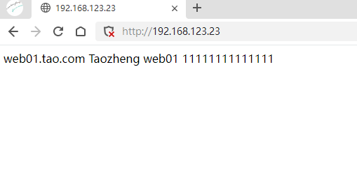
访问haproxy端的地址

测试01
测试02

关闭web01的httpd,就只显示web02的信息了

测试03

再次打开web02的httpd就可以两端都可以访问到

Haproxy端设置ssl

cd /etc/pki/tls/certs

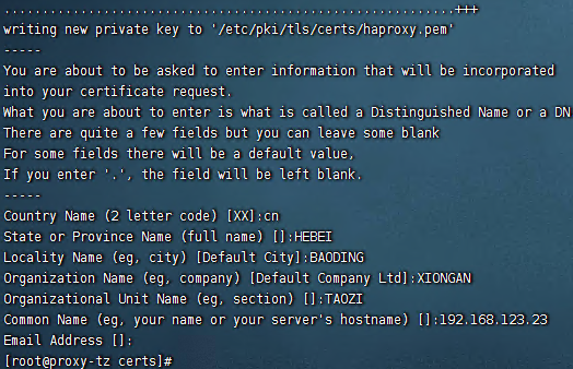
openssl req -x509 -nodes -newkey rsa:2048 -keyout \ /etc/pki/tls/certs/haproxy.pem -out /etc/pki/tls/certs/haproxy.pem \ -days 365
运行后如下图:
生成ssl

修改haproxy的配置文件

vim /etc/haproxy/haproxy.cfg

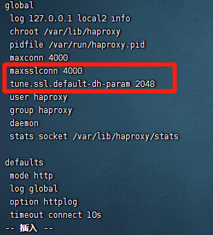
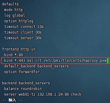
配置ssl
配置ssl

//* 设置 SSL 最大连接数

//* 设置 SSL 加密信息

//* 定义 SSL 监听的端口及秘钥所在路径及文件名

保存后重启haproxy

在放行443端口

firewall-cmd --add-port=443/tcp

之后测试打开ssl地址

测试04
测试05

]]>